


Penstocks are machines always present in any water system; their presence allows to control the passage of fluid through the interception and their conveyance. Penstocks allow, in fact, the opening and closing of passages inside the plant, being therefore of great importance in its management.
It is possible to manufacture penstocks of various types, each of them suitable to specific installation conditions. The main distinction in the classification of the penstocks regards the type of installation, which can be channel or wall mounted.
In the channel installation type the frame of the penstock is inserted and fixed inside a channel.
To make the anchoring of the frame possible and make sure that the net cross section of the penstock is not less than the dimensions of the channel itself, it is necessary to realize an external slot in the walls of the channel next to the point of installation. The frame of the penstock will be housed in the slot that will be later filled with grout. The frame of the channel mounted penstocks is suitably designed for this specific application to ensure a solid anchorage to the channel.
The driving control of the channel mounted penstocks can be supported by an upper crossbar or by a maneuvering column.
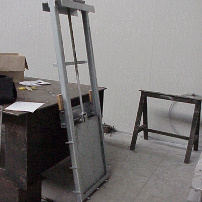
If the height of the channel is such that the door of the penstock completely lifted exceeds the operating floor it is necessary the use of an upper crossbar.

This case usually occurs for channels where the height of the channel is not so high than the water depth of the flow to intercept, and this is the most common case. If the height of the channel is such that the door of the penstock completely lifted does not exceed the operating floor it is appropriate to use the maneuvering column. This case, less frequently, occurs if the channel is very deep and the water depth in the channel is not very high.
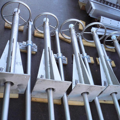
If the maneuvering column is used it is necessary to bear in mind that it can be wall mounted or floor mounted.
The wall mounting is realized when the column is anchored with a “L” shaped support on the final part of a wall, its fastening takes place with anchors on both the top of the wall and on its vertical part. In the case of floor mounting the column base plate is square and it is anchored and placed on the floor. In this last case the control rod of the penstock passes through a hole in the floor placed at the center of the column.
In the case of channel mounted penstocks the gasket is usually placed on 3 sides of the door (the bottom and the two vertical sides).
In the wall installation the frame is fixed to wall to allow the interception of fluid from pipes or openings in the mounting wall.
The frame in this case is suitably shaped for this application and the fixing to the wall is not made by grout but by means of anchors. The wall mounted penstock can be also used if the lower part of the pipe or the opening to close coincides with the bottom of the tank. In such a case to ensure that the net cross section of the penstock is not less than the dimensions of the pipe/ opening, it will be necessary to realize a slot on the bottom of the tank to house the lower part of the frame. In this case the frame will be fixed by means of anchors all along its entire perimeter except for the bottom which will be casted in the slot by means of filling concrete. The fixing of the bottom by anchors would not be possible, in fact, for the difficulty (sometimes impossibility) to make the fastening holes.
Also for wall mounted penstock the driving control can be supported by an upper crossbar or by a maneuvering column. If the installation level is such that the door of the penstock completely lifted exceeds the operating floor it is necessary the use of an upper crossbar. This case usually occurs for openings or pipes placed in shallow tanks. If the installation level is such that the door of the penstock completely lifted does not exceed the operating floor it is possible to use a maneuvering column.

This case, certainly more frequently, occurs if wall mounted penstock is installed to close pipes or openings placed at a certain depth, even very high, inside a tank. If the maneuvering column is used it is necessary to define if the maneuvering column is wall mounted or floor mounted.
In the case of wall mounted penstocks the gasket is mounted on the door and placed on 4 sealing sides of the same. In some cases the realization is 3-sided seal if the fourth side, the upper one, is not necessary.
Another important distinction to be made in the choice of a penstock regards its degree of automation, as it is possible to realize penstocks with manual control or by means of an actuator.
The manual penstocks are realized when the low degree of automation of the plant and the low drive frequency of the penstock make acceptable the fact that the same is manually controlled by an operator.

They can be made in the version with handwheel, or with gearbox and handwheel. The choice of the presence or not of the gearbox is carried out directly by SERECO technicians according to the force required for the operation and according to standards ANSI/AWWA C560-00, C540-02, C561-04 and C513-05. On request it is possible to install the gearbox even if it is not strictly necessary from the calculation.
Actuated penstocks are instead realized in case it is required an automated operation and the remote control. In this case it is possible to use a ON / OFF type control (standard solution) for the opening / closing of the penstock, or on request the modulating service by analog signal 4÷20 mA, that allows the continuous control on the position of the door. The actuated penstocks, finally, are always equipped with emergency handwheel mounted on the actuator.
Penstocks made by SERECO are designed and manufactured according to the directions of standards ANSI/AWWA C560-00, C540-02, C561-04 and C513-05. The main directions provided for by these standards are:

In the construction of penstock the gasket is fixed to the door so as to make the replacement easier when necessary, while the sealing surface is provided by the frame.
The door gasket used by SERECO in the standard construction of penstocks is EPDM (Ethylene-Propylene Diene Monomer) extruded with hollow music note shape. It is a polymer with excellent deformability and high mechanical resistance which make it then suitable for the application. The gasket, in fact, being a hollow profile, deforming and compressing during the closing of the door ensures the seal in any operation condition. The chosen material is also very resistant to any climatic condition, and it is able to work at temperatures ranging from +150°C to -50°C. Finally, it is suitable for aggressive fluids such as domestic sewage and various types of industrial sewage.
For applications with presence of solvents or fuels it is normally used the hollow profile gasket but in NBR instead of EPDM. The size of the section of the gasket is chosen by SERECO each time according to the actual operating conditions of the penstock and according to the selected model.
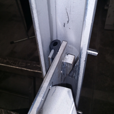
The penstocks manufactured by SERECO are rising screw type in the standard construction. This design choice is linked to the greater simplicity of detection of the current position of the penstock. In rising screw type solution, in fact, the screw is visible inside the transparent cover that allows to determine immediately the current position of the penstock door even in cases where this is not immediately visible.
The maneuvering screw is in left-handed TPN profile, so as to ensure that the opening of the penstock takes place by turning the handwheel counter-clockwise as per standards ANSI/AWWA C560-00, C540-02, C561-04 and C513-05. The standard construction of manoeuvring screw is AISI 420. This material is suitable because its martensitic structure ensures high mechanical properties and at the same time reduces the risk of seizure even in conditions of poor lubrication.
The penstocks can be manufactured with different types of materials and surface treatments depending on the type of fluid to intercept. The main realizations are in carbon steel hot dip galvanized, painted, stainless steel AISI 304, AISI 316L, DUPLEX or aluminum. Construction in other materials is possible on demand.